inquiry
Leave A Message
If you are interested in our products and want to know more details,please leave a message here,we will reply you as soon as we can.
submit
Home

automatic compensation grinding robot

automatic compensation grinding robot

  • Floating Grinding, Rigid Cutting, and Compliant Contact: Why One Force Setting Cannot Finish a Casting
    Nov 02, 2026
    Floating Grinding, Rigid Cutting, and Compliant Contact: Why One Force Setting Cannot Finish a Casting   The shop-floor habit that gets the physics backwards When a foundry looks at a grinding cell for the first time, two numbers usually dominate the conversation: arm payload and spindle power. Bigger looks safer. After commissioning, the program often fails for the opposite reason. The machine had enough force. It applied that force in the wrong place. Cutting a remaining iron gate wants the tool held in, feed held steady, wheel or mill actually biting. Run the same press into a thin corner of an aluminum oil pan and the wall yields before the path ends. Waves show up. Local over-grind follows. A grinder with an angle grinder in hand backs off without thinking. A robot does not, unless that backing-off is written into the control. So at least three contact states have to be kept separate: rigid cutting, floating grinding, and compliant (torque-limited) contact. They sound like brochure features. On the floor they are three different ways the tool meets metal. Rigid cutting is for stock that still has to be removed Gate stubs, heavy flash, local swell: the material is still there, and it is often thicker and harder than the casting body. The job is not to polish a surface. It is to take a lump off. The path has to stay put. The spindle has to bite. Table and arm cannot fold when the cut starts. That is why a builder such as Anhui Neview talks about stiffness and payload together. On a DR-class iron cell, designing table and arm around a 200 kg class load is not a round number for a catalogue. Gate-root cuts can push contact force into a high measured range. If the structure is soft at that point, the path drifts, the wheel chatters, and consumable life collapses. Rigid cutting has limits. If the locating scheme rocks, or the clamp only holds one corner, a heavy cut will walk the part in the fixture. If the stub sits next to a machining datum, an uncontrolled depth takes tomorrow’s stock. Those zones want rigidity. They do not want a floating head with its full stroke unlocked — extra float makes depth a guess. Float keeps contact. It does not hand accuracy to chance A floating spindle gives the tool a short allowed travel so it can stay on a surface that is not the CAD surface. Draft, shrink, and uneven flash mean a theoretical path kisses air in one spot and slams in the next. Float is there so contact continues inside a band, not so the robot can ignore coordinates. Mega structural die castings make the split obvious. Parting lines, gates, and rib crossings on one shot can differ by a visible step. Neview’s large-part layouts put floating and rigid spindles on the same cell because one casting contains stock that must be cut off and skins that will not survive a hard pass. One spindle mode for the whole part either refuses the gate or breaks the wall. Float is also misread as a substitute for path compensation. It is not. Float covers local height and continuous contact. Systematic shrink, a shifted datum, or a batch that leans the same way still needs measured offset applied to the path. Float is contact. Compensation is location. Running only one of them shows up quickly in scrap. Compliant contact is loop control, not a soft machine Some castings fight displacement sensors. Thin walls move when clamped and move again when cut. The offset you measured is not the offset that exists three seconds later. Rewriting the path from a stale measurement makes the motion worse. Compliant contact takes another route. Instead of pinning the tool to a position target, current, position, and torque loops keep the contact force inside a band. Change the band and the same taught path behaves differently on a different wall thickness. Aluminum housings, some thin die-cast skins, and ribs that like to give away are the usual candidates. Soft has a cost. Too little force and flash remains. A little too much and the wall dished in — shiny, and wrong. Technicians who only know how to lower torque end up with parts that look processed and still fail a fingernail check on the parting line. The aim is a bounded force, not an apology. Change the alloy and the mix of the three modes has to change Gray or ductile iron: gates, risers, and parting flash dominate. Wheels and burrs do most of the work. Rigid cutting usually takes the larger share. Iron is relatively brittle. The shape stays when you push. What you fear is vibration and a wheel that sheds, not a wall that folds. Aluminum: the same flash sits on a wall an order of magnitude thinner. Over-grind, chatter marks, and a rib root cut too lean matter more than raw removal. Float and compliance take more of the cycle. Disc mills and profile cutters show up more often than a hard wheel leaned into the part. Steel: harder metal, nastier scale and burned-on sand. Stiffness and spindle power come up before “soft touch.” Compliance can finish a contour. It will not remove a steel gate on a serious cycle time without killing the tool. Copying a DR iron parameter set onto an MR aluminum cell, then blaming the robot for “not knowing aluminum,” is a category error. The contact strategy moved shops without moving with it. Complexity is not a reason to open every float and soften every torque A complex casting still has three kinds of real estate: process stock that must disappear, fits that must keep size, and blends that only have to look continuous. Maximum float plus minimum torque usually sacrifices the fit first and leaves the stock. Zoning is dull and it works. Gate roots stay rigid. Long flash runs use float to keep the tool on the line. Thin corners switch to torque limit. The program looks less elegant. It matches how a good grinder already works by hand. High-mix, low-volume shops should also keep zoning modest. Every zone is another teach and another buy-off. Some plants are better off locking 80 percent of the repeat surface with rigidity plus compensation, and leaving two awkward spots for a person, instead of specifying four spindles and full float on day one. Over-grind, under-grind, and chatter usually point back to force Over-grind likes thin walls, inside corners, and surfaces that already had a rough pass. The path still assumes the largest as-cast envelope, and the force never came down. Compensation that only fixes a bulk offset will still dig into a local dish. Under-grind leaves a step on the gate or a wire of flash. Sometimes the wheel is dull. Often the cut needed rigidity and the float pushed the tool off at the exact place the metal was thickest. Chatter can be structure, spindle balance, wheel runout, or a clamp that breathed. Adding float because a surface buzzed does not make a damper. It changes the shape of the vibration. Loose structure still has to be tightened. Do not only ask whether the cell “has float” Better questions: how much stroke, and can it lock to rigid; is torque one global value or zone-based; can compensation and float run together, and in what order; on a multi-spindle or mega-part cell, which spindles are rigid and which float; how many sample loops a thin-wall part usually needs before the path is released. Neview lists measured error compensation and compliant contact as two capabilities because foundries meet two castings: parts you can measure, and parts that change while you cut. Measurable parts get a path rewrite. Unstable parts get a force loop. Asking how both are implemented is more useful than circling the word “smart” on a slide. Some stations should not get a floating head A single part number with tight as-cast consistency and a trustworthy datum can live on a rigid spindle and a honest fixture. Extra float is another mechanism in a dusty cabin and another parameter that can drift after a weekend. A family of similar parts with wild flash, or die-cast batches whose shrink walks around, will burn teaching time if the tool cannot give or the path cannot shift. The practical test is still crude: does a skilled grinder ease off at this spot, or lean in because the metal will not yield? Ease off, and the cell needs give or a force cap. Lean in, and it is a rigid cut. Close on selection, not on a slogan In casting grinding, force shows up before brand. A gate has to come off, a thin wall has to stay, and a flash line has to be followed. Those three jobs rarely share one contact stiffness. Comparing rigid cutting, floating contact, and torque-limited blending side by side gets a buyer closer to the floor than comparing arm kilograms alone. Cells that keep running are usually not the ones with every function turned to maximum. They are the ones that know which segment must stay hard, which segment may follow, and which segment must cap force. Spindle kilowatts, grit, and cycle time come after that argument is settled.
    Read More
  • On mixed-SKU casting grinding, changeover time is rarely the robot program
    Oct 15, 2026
    On mixed-SKU casting grinding, changeover time is rarely the robot program Many foundries size a grinding cell on one representative part. Three months after start-up, output is eaten by two-hour changeovers — and by the half-shift of hand touch-up that follows. A single-part cycle chart often dies on a mixed line Quotes for automated grinding are almost always built on one part: flash length, gate stub size, minutes per cycle, whether dual stations overlap load and grind. The spreadsheet looks clean. The shop floor runs a different clock. Valve bodies in the morning, brackets after lunch, two pallets of housings squeezed in the next day. The representative cycle time is still true. What is not true is dividing 480 minutes by that number. Subtract fixture swap, tool swap, probing, first-article grind, and quality release. That remainder is the real shift. People call this “slow program change.” Calling a program on the HMI takes seconds. Locating the part, matching the tool, keeping the compensation datum, and getting first-article sign-off are slower. Three of those four have little to do with the robot brand. Changeover is four layers, not one motion Shops treat changeover as stop, swap, run. It is at least four layers. Program: path, spindle speed, feed, force or compensation settings. This layer is fast if programs live under a part number, not in someone’s teach-pendant backup. Fixture: clamps, locators, jaws, or a complete tooling plate. Casting sand wears pins. A hole that matched the drawing in month one does not match in month six. Tool: wheels, burrs, mills, flap wheels are not universal. A hard wheel sized for iron gate stubs will tear an aluminum skin. An aluminum face mill on ductile-iron flash goes dull in minutes. A tool change usually needs balance or a touch-off. Skip that and the first pass vibrates the new path off. Datum: probe points, vision templates, safe retracts. Points that sat on a valve body last week may land on flash or empty air on this week’s bracket. A wrong probe point is worse than no compensation. If any layer is unprepared, a “15-minute changeover” on the form becomes an hour. Many acceptances run eight hours on one SKU. Changeover is never in the scorecard. Fixtures are where most plants actually lose the hour Stable families can live with a self-clamping fixture or a press-down unit and only swap locators. Plants with scattered geometries are different. A valve uses a register, a bracket uses two pads, a housing sits on the cavity. A “universal fixture” usually locates universally badly. Simple pins are cheap and quick to change. They are also sloppy once parting-line shift shows up. Hole-break edges then vary lot to lot, machining sends parts back, and the simple fixture grows extra stops until it is no longer simple. Self-clamping tooling locates well and behaves like a small machine of its own when you swap it. Lead time is long, storage is real, and door-swing interference on a three-station table often appears only at install. AI grinding’s honest benefit on changeover is fewer hard locators. A tray or a coarse stop can be enough for the vision system to find pose. That does not turn a thin aluminum housing into a rigid body. Vision finds the part. Cutting force and chatter still need support. When tools lock you to a material family, changeover becomes a cell change Iron cells are built around wheel load and stub cutting. Aluminum cells more often run face mills, cutters, or belts. Steel adds hardness. Hanging an iron wheel and an aluminum mill on one spindle is possible on paper. Dust mix, filter fire risk, hood opening, and airflow are designed around one chip type. Few plants keep that mix for long. Mixed SKUs therefore does not mean one cabin for every alloy. The cheaper split is usually iron on one cell, aluminum on another, then size bands inside each family. Changeover stays inside a family where fixtures and tools still share something. Forcing a ductile valve and an aluminum housing through the same cabin puts spindle maps, dust mode, guarding, and base plates on the changeover list. The machine you saved is paid back in lost hours and process risk. A stored program and a re-taught program are two different factories Someone who can teach a robot is not the same as someone who owns a program library. Names like “valve2”, “valve2-fix”, “final” mean nobody will call the file three months later. Changeover becomes: open the nearest path and re-touch the critical points. Compensation belongs with the part number: probe coordinates, allowable offset, force cap. Store only the path and the probes stay where the last product left them. First article either cuts into parent metal or leaves a ring of flash. A Chinese teach pendant shortens training. It does not replace version control, first-article records, or a name on the last path edit. When the senior operator is off, that gap hurts more than a spindle alarm. Vision shortens finding the part. It does not skip process prove-out High mix, modest volume is the usual reason to look at AI grinding. You weld fewer hard fixtures. For housings and brackets that do not justify a full clamp set, that reason holds. What does not hold is the hope that vision makes changeover a start button. The template says which product this is. It does not say how tall this gate stub grew after a tooling wear week. Tool strategy and compensation still sit per family. A new part still needs a first article and a feed tweak. Treat AI as “no process work” and you will rework. It cuts fixture count and search time. The process window stays. On tight windows, first-article time after a change can exceed the fixture swap itself. Not every high-mix shop should chase one cell for the whole list Mixing on one cell usually needs several conditions at once: same material family, size inside one table, similar burr shape so tools can be shared, enough daily volume to keep changeover count tolerable, and a shop willing to keep fixture and program books. Bad mixes are equally concrete: iron with aluminum, stub cutting with cosmetic faces, prototypes stealing a production cell, downstream machining that already uses the ground edge as a datum. A second cell looks expensive until you add changeover, touch-up, and scrap. A middle path is common: one cell locked on two similar runners that make most of the tons, a third geometry left to a bench or a vendor. Automation does not have to cover every drawing number. Covering the two numbers that are 80% of output is often the better buy. If the changeover sheet is vague, cell speed does not matter On the machine side: dual stations so the door is not the cycle, HMI recall by part number, fixture quick-change interfaces, at least a quick-change tool flange, compensation stored with the program. Dedicated foundry cabins tend to hold these together because table, door, and dust are designed as one cycle. A general-purpose robot in a fence usually does not. The plant owns the other half. Fixtures wiped before the swap, pins replaced on a calendar, wheel remaining diameter written down, first-article dimensions listed, a rule for whether a bad part means a path edit or a locator check. Without that sheet, a twenty-minute vendor changeover still dies in the afternoon. Scheduling has to change with it. Three unrelated geometries in one shift will beat any spindle. Run a family together. Park changeovers at shift start. “Cut over any time” is a sentence from a presentation, not from a grinding bay. Ask how many times a day you change before you ask if the robot can grind Whether a grinding robot can physically cut a casting is the first sourcing question. On a mixed line it is not the deciding one. The deciding questions are whether those drawing numbers belong in one cabin, and which of the four changeover layers you have actually prepared. A program that appears on the screen only proves the integrator shipped a file. Repeatable location in twenty minutes, tools that stay inside one material family, probe points that travel with the SKU, and a signed first article — that is changeover capability. Miss one, and you are back to the single-part chart that never described the shift.
    Read More

  • The Era of Green Foundries: How Grinding Robots Cut Energy & Consumable Costs
    The Era of Green Foundries: How Grinding Robots Cut Energy & Consumable Costs
    Jul 22, 2026
    How Grinding Robots Cut Energy & Consumable Costs Against the backdrop of global carbon neutrality and green manufacturing, foundries must balance high output with lower energy consumption and environmental sustainability. Post-casting grinding—traditionally a major source of energy use and consumable waste—is undergoing a green transformation through robotic automation. 1. Optimizing Grinding Paths to Extend Abrasive & Tool Life In manual grinding, uneven force often leads to premature wheel wear or tool breakage. Grinding robots utilize constant force and surface speed control to wear abrasives down evenly, boosting tool life by over 30% and directly trimming consumable budgets. 2. Cutting Factory Energy Consumption & Dust Collection Load Unlike traditional open-shop dust extraction, robotic grinding workstations feature enclosed dust containment enclosures. Paired with localized suction systems, they trap particulates at the source while cutting power usage for facility-wide HVAC systems. 3. Enhancing Workplace Health to Pass Global ESG Audits Global buyers—such as automotive OEMs and heavy machinery leaders—increasingly weigh EHS and ESG (Environmental, Social, and Governance) standards during supplier audits. Implementing grinding robots cleans up the shop floor, lowers occupational safety risks, and cuts waste, giving foundries a distinct edge in securing high-value international contracts.
    Read More
  • Grinding Robots: The Core Driving Force for Efficiency Transformation in the Foundry Industry
    Grinding Robots: The Core Driving Force for Efficiency Transformation in the Foundry Industry
    Jun 02, 2026
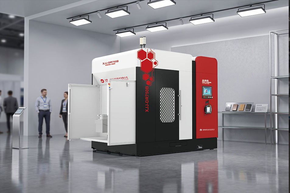
    Grinding Robots: The Core Driving Force for Efficiency Transformation in the Foundry Industry In the increasingly competitive foundry industry, grinding robots are gradually becoming the key to improving production efficiency and product quality. Neview's grinding robots stand out among many similar products with cutting - edge technologies.   The unique eight - axis seven - linkage structure of Neview's grinding robots endows them with highly flexible operational performance. This structure enables the robots to operate in coordination like human hands, achieving precise grinding at complex angles and positions. It greatly improves the grinding coverage rate and shows obvious advantages in the grinding of complex castings.   Ultra - high rigidity and large load - bearing capacity are also their highlights. Taking the DR - 750B model as an example, both the workbench and the robotic arm can bear a 200 - kg - class load. When facing the cutting and grinding tasks of large riser stubs, it can perform stably, ensuring that the grinding quality is not affected by the load.   The automatic error detection and compensation system is crucial for ensuring accuracy. Through displacement sensors, it can detect the differences of workpieces in real - time. The system's background quickly calculates and automatically corrects the grinding path to adapt to the inevitable dimensional errors during the casting process, guaranteeing the grinding accuracy of each product.   In the grinding of easily deformed workpieces, the intelligent compensation and flexible fitting technology of Neview's grinding robots plays an important role. By controlling the current loop, position loop, and torque loop, it realizes flexible grinding. It can precisely adjust the fitting force according to the material and shape of different workpieces, avoiding damage to the workpieces.   With these advanced technologies, Neview's grinding robots bring significant benefits to foundry enterprises. They not only improve grinding efficiency and reduce labor costs but also enhance the overall product quality with stable high - precision grinding, strengthening the market competitiveness of enterprises.
    Read More
  • Unlocking the Potential of Grinding Robots: Neview Empowering Foundries
    Unlocking the Potential of Grinding Robots: Neview Empowering Foundries
    May 18, 2026
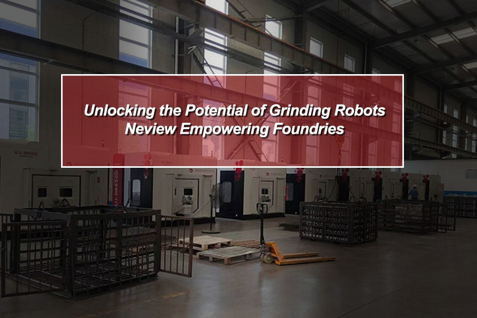
    Unlocking the Potential of Grinding Robots: Neview Empowering Foundries In the foundry industry, fully tapping the potential of grinding robots is crucial for enhancing the overall competitiveness of foundries. The Neview grinding robots provide strong support for foundries to achieve this goal through a series of advanced technologies and functions.   The eight - axis seven - linkage structure equipped in the Neview grinding robots is one of their core advantages. This complex and sophisticated structure enables the robots to move and operate freely in multiple dimensions, achieving precise grinding of various complex - shaped castings. Compared with traditional grinding equipment, it can complete grinding tasks more quickly and accurately, greatly improving grinding efficiency and quality. For example, when processing castings with irregular surfaces, the eight - axis seven - linkage structure allows the robots to easily fit the casting surface, ensuring that every part is evenly ground.   The intelligent compensation and flexible fitting technology is another key feature of the Neview grinding robots. For easily deformed castings, traditional grinding methods often cause damage to the castings. However, the Neview grinding robots can automatically adjust the grinding force and path according to the real - time state of the casting by intelligently controlling the current loop, position loop, and torque loop, achieving flexible grinding and effectively protecting the castings from damage. This technology not only increases the casting yield rate but also broadens the application scope of the robots in grinding castings of different materials and shapes.   The automatic error detection and compensation system is an important guarantee for the Neview grinding robots to ensure high - precision grinding. During the casting process, there may be small deviations in the size and shape of the castings, which will affect the grinding accuracy. This system uses high - precision displacement sensors to detect these deviations in real - time and automatically corrects the grinding path through background algorithms, ensuring that the robots can always grind according to an accurate trajectory, thus guaranteeing the stability and consistency of product quality.   In addition, the design of the Neview grinding robots focuses on seamless integration with the production processes of foundries. It can be customized according to the actual needs of foundries, and whether it is used for single - machine operation or integrated into an automated production line, it can exert its maximum efficiency, bringing efficient and stable grinding solutions to foundries.
    Read More
  • How Grinding Robots Reshape the Production Advantages of Foundries?
    How Grinding Robots Reshape the Production Advantages of Foundries?
    Apr 30, 2026
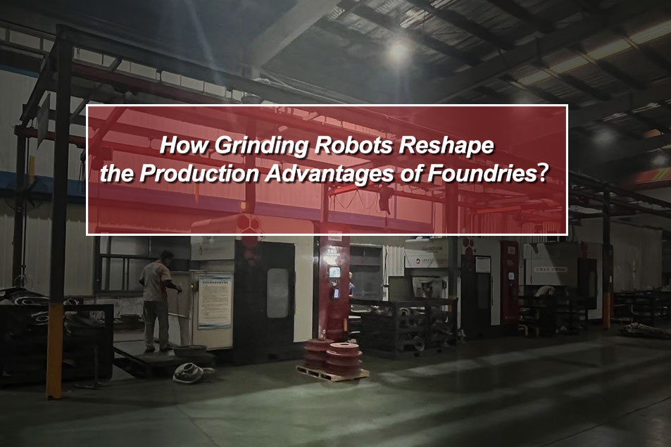
    How Grinding Robots Reshape the Production Advantages of Foundries? In today's highly competitive foundry industry, foundries need to constantly seek innovation and breakthroughs to enhance their production advantages. The grinding robots of Anhui Neview Automatic Technology Co., Ltd. are becoming the right - hand assistants for many foundries to achieve this goal.   Firstly, grinding robots significantly improve production efficiency. The eight - axis seven - linkage structure and two - hand coordinated operation mode of Neview grinding robots enable them to handle grinding tasks on multiple parts simultaneously, greatly shortening the grinding time for a single casting. Compared with manual grinding, robots can work continuously without fatigue and are not affected by external factors, ensuring the continuity of production. This allows foundries to complete more orders within the same time and meet the market's demand for product quantity.   Secondly, the grinding quality has been qualitatively improved. The grinding path of the robot is precisely controlled by a program. Combined with the automatic error detection and compensation system, it can adjust grinding parameters in real - time according to the actual situation of the casting, ensuring that each casting can meet a consistent high - quality standard. Whether it is a complex geometric shape or a surface with high - precision requirements, the grinding robot can handle it accurately, effectively reducing the defective rate and improving the overall quality level of products, thus enhancing the foundry's competitiveness in the market.   Furthermore, the use of grinding robots helps foundries reduce costs. Although purchasing grinding robots requires a certain initial investment, in the long run, it reduces the dependence on a large number of workers and lowers labor costs. Moreover, due to the improvement of grinding quality, the rework and scrap costs caused by defective products are reduced, further improving the economic benefits of the enterprise. At the same time, the maintenance cost of the robot is relatively stable and highly predictable, facilitating cost control for foundries.   In addition, grinding robots also improve the working environment of foundries. Traditional grinding work is accompanied by a large amount of dust and noise, which is harmful to the health of workers. The application of robots liberates workers from harsh working environments, which is conducive to enterprises attracting and retaining talents and promoting the sustainable development of the enterprise.   In summary, Neview grinding robots comprehensively reshape the production advantages of foundries by improving production efficiency, enhancing grinding quality, reducing costs, and improving the working environment, laying a solid foundation for the long - term development of foundries.
    Read More
  • Human-Robot Collaboration: The Most Practical Path for Automated Grinding Today
    Human-Robot Collaboration: The Most Practical Path for Automated Grinding Today
    Dec 01, 2025
    Human-Robot Collaboration: The Most Practical Path for Automated Grinding Today Many customers ask, “Can we achieve fully unmanned grinding?” The reality is: full automation isn’t feasible yet. The most effective approach today is human-robot collaboration.  1.Why Is Full Automation Difficult?   Castings vary in deformation, batch differences, and irregular flash shapes. Robots excel at repetition, not judgment. 2.Human-Robot Collaboration Is More Efficient The optimal workflow: manual loading/unloading, NEVIEW robots handling the main grinding paths, and humans handling the few ultra-complex areas. 3.Robots Handle the Standardized 80% NEVIEW’s high-rigidity robotic arm and automatic path correction cover most standardized zones effectively.  4.Safety Benefits Are Underrated   Dust, noise, and vibration can harm workers. Robots isolate these hazards inside a fully enclosed safety cell. 5.More Predictable ROI   With faster deployment and lower risk, this model offers predictable ROI and is widely accepted in global factories. Real automation isn’t about replacing people — it’s about letting humans and robots each do what they do best. NEVIEW’s automation solutions are helping foundries worldwide achieve more stable and modern production.
    Read More
  • Smart Grinding for Aluminum Die-Cast Parts: Boosting Efficiency and Quality
    Smart Grinding for Aluminum Die-Cast Parts: Boosting Efficiency and Quality
    Nov 17, 2025
    Smart Grinding for Aluminum Die-Cast Parts: Boosting Efficiency and Quality   Aluminum die-cast parts are prone to deformation and sharp edges. Manual grinding is time-consuming and may generate defective products. NEVIEW smart grinding robots use high-precision laser detection and force-control systems to identify burrs and workpiece geometry, dynamically adjusting angles and pressure for precise deburring and smooth surfaces. Automated systems complete multi-angle grinding in one fixture, increasing throughput by 30–50% while reducing labor costs. With data monitoring and smart path optimization, manufacturers achieve consistent quality, stable production, and energy efficiency. Applications: automotive parts, home appliance aluminum parts, and industrial aluminum castings.  
    Read More
  • ROI of NEVIEW GRINDING ROBOT
    ROI of NEVIEW GRINDING ROBOT
    Oct 23, 2025
    ROI of NEVIEW GRINDING ROBOT   One key question many companies ask: How long does it take for a grinding robot to pay for itself? The answer: usually less than two years. Investment Benefits Labor Savings – One robot can replace 3–5 workers Lower Scrap Rate – Reduced human error, improved yield Higher Productivity – Efficiency increased by 2–3 times Hidden Cost Savings – Fewer accidents and downtime losses Case Reference Some customers report that after deploying NEVIEW GRINDING ROBOT, production costs dropped by 20–30% on average, while order delivery capacity significantly increased. Conclusion An investment in NEVIEW GRINDING ROBOT is not just about reducing costs—it’s about boosting competitiveness and achieving real ROI through intelligent manufacturing.
    Read More

leave a message

leave a message
If you are interested in our products and want to know more details,please leave a message here,we will reply you as soon as we can.
submit
Contact Us: judy@ahxjj.cn

home

products

WhatsApp

Contact Us