Sep 03, 2026
Failure Analysis and Countermeasures for Automated Deburring of Die Castings
AbstractAutomated deburring of die castings is theoretically considered easier to implement than for iron or steel castings because die castings have better surface quality and burrs are concentrated at relatively fixed locations such as parting lines, gates, vents, and ejector pin marks. However, actual operating data from multiple die casting shops show that robot deburring cells commonly experience missed spots, over-grinding, tool collisions, and yield degradation after only three to six months of production, with some equipment eventually idled or reverted to manual operation. This article analyzes the process characteristics of die casting production and identifies three core factors causing automation failure: burr size variation due to die wear, lack of reliable positioning datums on raw parts, and insufficient deburring tool management. The study argues that the prerequisite for successful die casting deburring automation is not higher robot accuracy or faster force control response, but rather the establishment of a preventive die maintenance system, reliable workpiece positioning solutions, and closed-loop tool life management. The article concludes with improvement paths and implementation recommendations for different die casting production scenarios.
Keywordsdie casting deburring automation; burr consistency; die wear; positioning datum; tool management
1 IntroductionDie casting produces parts with relatively high dimensional accuracy, good surface finish, and fast cycle times, widely used in automotive, telecommunications, power tools, and home appliance industries. After ejection, die castings typically require removal of gates, vents, flash, and ejector pin protrusions, collectively referred to as burrs. Manual deburring has long relied on pneumatic files, rotary burrs, and sandpaper, with high labor intensity, obvious dust and noise hazards, and poor consistency. Therefore, the die casting industry has a strong practical demand for deburring automation.
From a technical perspective, burr positions on die castings are relatively fixed, theoretically making them suitable for automated removal by robots with floating tools. However, in actual projects, many die casting plants have invested hundreds of thousands or even millions of RMB in robot deburring cells, only to encounter various problems after a few months of operation: some products show rising missed-spot rates requiring full manual inspection and repair; some suffer over-grinding leading to scrap; some experience frequent tool collisions causing spindle damage. These problems erode management confidence in automation, and equipment gradually sits idle.
This article analyzes the deep causes of die casting deburring automation failure based on investigations and project reviews in multiple die casting shops. The analysis is not limited to the robot itself but covers die casting molds, raw part condition, positioning methods, tool consumption, and on-site management, aiming to provide actionable improvement directions for die casting plants.
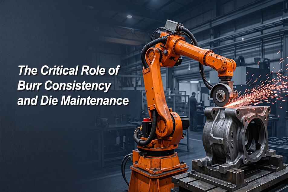
2 Burr Size Variation: The Direct Consequence of Die WearBurrs on die castings primarily form at the parting surface. Die casting molds are subjected to alternating clamping force and thermal stress from high-speed, high-pressure molten metal injection, causing wear, edge collapse, and localized depression on the parting surface. New molds or freshly repaired molds have tightly closed parting surfaces, with flash thickness typically between 0.1 mm and 0.3 mm—thin and uniform, allowing robots to remove it stably with fixed trajectories and minimal floating compensation. But as mold usage accumulates, the parting surface gap gradually increases, and flash thickness can grow from 0.3 mm to over 1 mm, sometimes exceeding 2 mm in severe local areas.
This variation in burr thickness is devastating to robot deburring. Under fixed trajectory mode, the robot follows preset paths and pressure. When burrs suddenly thicken, if the force control system does not respond quickly enough, the tool will either over-cut the workpiece body or under-cut the burr. Even with force-controlled spindles, response time is typically in the tens of milliseconds, offering limited adaptability to sudden burr changes. Moreover, if force control parameters are set too sensitively, vibration occurs even in normal burr areas, affecting surface quality.
The fundamental solution is die maintenance. Die casting plants should establish a preventive die maintenance system, incorporating parting surface flatness inspection into daily checks. Specific practices include: inspecting parting surface wear every certain number of shots (e.g., 5,000 to 10,000 shots, depending on product size and alloy type), measuring parting surface gap with feeler gauges, repairing collapsed edges by welding and grinding, and promptly replacing worn inserts and ejector pins. The goal is to control burr thickness within a preset range, such as no more than 0.5 mm. Only when burr size is stable can robot trajectories and force control parameters remain effective over the long term.
3 Lack of Positioning Datum: Strict Requirements on Raw PartsRobot deburring demands far higher workpiece positioning accuracy than manual work. Manual operators can watch the workpiece and adjust file angles accordingly, while robots rely on preset coordinate systems. If the workpiece is not placed in a consistent position each time, the robot grinding trajectory will deviate from the actual burr location.
Die cast raw parts usually enter deburring directly without machining, lacking precision datum surfaces. Fixtures often locate on raw surfaces, ejector pin bosses, gate stubs, or sidewall profiles. These features have draft angles, ejection deformation, and position deviations. For example, ejector pin boss height may vary due to ejector mechanism wear, gate stub length differs due to injection parameter fluctuations, and raw surfaces warp from uneven shrinkage. These accumulated deviations can cause the actual workpiece position on the fixture to differ from the theoretical position by 0.5 mm to 2 mm. For deburring processes requiring accuracy within 0.3 mm, such positioning error is unacceptable.
There are several ways to solve the positioning problem. First, control the tolerances of key locating features at the die casting stage, such as designing dedicated locating bosses on the mold and stabilizing their dimensions through injection parameters. Second, add a simple machining operation before deburring to mill a flat datum or drill a locating hole, providing a stable reference for the robot. Third, use vision guidance for rough position compensation, where cameras recognize workpiece contours or feature points, calculate offsets, and correct robot trajectories. Vision solutions face interference from oil, reflections, and surface oxidation color differences in die casting shops, and their recognition stability still needs improvement, making them more suitable as auxiliary means rather than the sole dependency.
4 Lack of Tool Management: An Open-Loop System Causes Yield DecayDie castings are primarily aluminum and zinc alloys with relatively low hardness, but rotary burrs, grinding discs, and flap wheels still wear. Aluminum has a special problem: aluminum chips tend to adhere to tool surfaces, forming built-up edges that reduce cutting efficiency and scratch workpiece surfaces. If tool condition is not managed, robot deburring quality gradually declines with running time, dropping from initial pass rates above 95% to 80% or lower.
Most die casting plants pay insufficient attention to tool management. In manual deburring, workers judge tool sharpness by feel and replace dull tools casually without cost awareness. But once a robot deburring cell is established, tool replacement must be institutionalized. Without tool life records and condition monitoring, the robot becomes an open-loop system: inputs are raw parts and tools, output is the deburred workpiece, but there is no feedback in between, and quality decay cannot be detected in time.
Improvement measures include: establishing a tool life statistics table recording the number of parts ground and replacement time for each tool; monitoring spindle current trends and prompting tool replacement when current drops significantly or fluctuates abnormally; for high-volume products, configuring automatic tool changers or multi-station tool magazines to reduce manual intervention. Tool costs should be included in the operating cost accounting of the automation system, and die casting plants must not ignore this item when calculating return on investment.
5 Application Scenario Analysis and Implementation RecommendationsDie casting deburring automation is not suitable for every product. Conditions favoring automation include: single product with high volume, annual output exceeding 50,000 pieces; a sound die maintenance system with controlled burr thickness variation; burr positions concentrated in robot-reachable areas; and product geometry allowing reliable positioning; product design tolerating certain deburring variation.
For multi-variety small-batch production or severely worn dies, blindly adopting robot deburring carries high risk. It is better to start with local automation on the most regular and concentrated burr locations, such as gate sawing or parting line grinding, while keeping other areas manual and transitioning gradually. Before investment, conduct a burr consistency test: collect burr height data from at least three batches with thirty pieces per batch, calculate mean and standard deviation, and use the results to set trajectory compensation amounts and force control parameters.
6 ConclusionThe main reason die casting deburring automation fails is not immature robot technology but insufficient process stability. The solution path must address die maintenance, raw part positioning, and tool management to establish a closed-loop control system. Only when burr size variation is controlled, positioning is reliable, and tool condition is manageable can robot deburring achieve long-term stable operation. Die casting plants should include die maintenance costs and tool management costs in total investment evaluation when making automation decisions, avoiding the mistake of only calculating equipment purchase price while ignoring operating costs.
Read More




 IPv6 network supported